Why would I use Petrolog if I can use different modelling software?
We are often asked, “Why would I use Petrolog if I can use MELTS?”. If you are interested in what makes Petrolog different from other crystallisation modelling software, then read on!
GENERAL
2/29/20249 min read
Petrolog4 is not just a crystallisation modelling software – it offers an expanding range of petrological and geochemical tools, as explained further in this article.
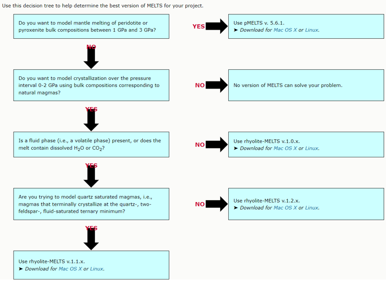

Figure 1. A decision tree for selecting a suitable version of MELTS from https://melts.ofm-research.org/MELTS-decision-tree.html.
Modelling of crystallisation
Petrolog4 offers an algorithm for modelling crystallisation that is not linked to specific models of mineral-melt equilibrium (MME), in other words, the algorithm is model-independent (although there are of course certain requirements on the types of MME models that can be included in Petrolog4). As a result, Petrolog4 can offer users a potentially unlimited choice of published MME models to be included in calculations.
The above is an important difference between Petrolog4 and other crystallisation modelling software that all offer a fixed model that describes equilibrium between melt and minerals/phases included in the software. The algorithm that is used by the software to perform crystallisation calculations is tailored to the included model. Examples of such software include MELTS and COMAGMAT (Figs. 1 and 2).
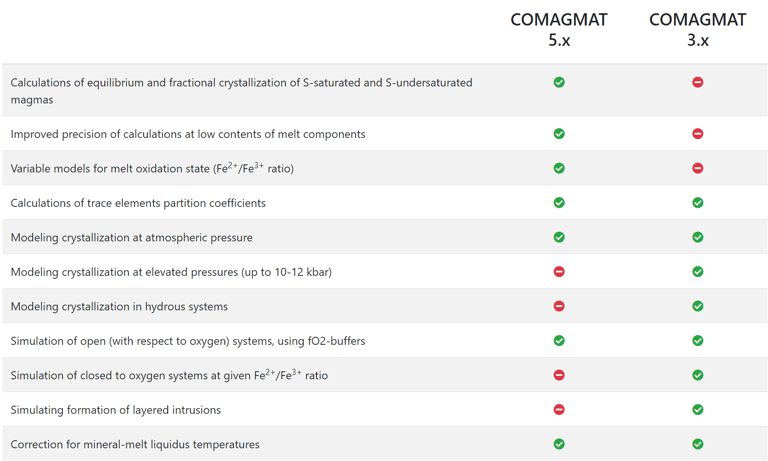
Figure 2. Comparison of COMAGMAT versions from https://comagmat.web.ru/apps-comagmat.html.
Petrolog4’s approach to modelling crystallisation
To be compatible with the Petrolog4’s algorithm, an MME model must be able to accept melt composition and, optionally, pressure and other intensive parameters such as oxygen fugacity, as its input parameters. The MME model cannot require temperature or the mineral composition as input parameters.
Based on the input parameters, the MME model must be able to calculate the temperature at which the mineral would crystallise from the given melt composition (i.e., liquidus temperature of the melt), and the composition of the mineral.
The Petrolog4’s algorithm requires that the MME model is able to calculate liquidus temperature not only for the range of melt compositions where the mineral is on the liquidus, but also for melt compositions outside the stability region of the mineral (temperatures calculated for melt compositions outside the stability region of the mineral are called pseudo-liquidus temperatures (PLTs) ).
Any MME model that satisfies the above requirements can be incorporated into Petrolog4, regardless of the internal workings of the model.
Petrolog4 (v.4.0.6) offers 16 models of olivine-melt equilibrium; 10 models of plagioclase-melt equilibrium; 9 models of clinopyroxene-melt equilibrium; 5 models each of orthopyroxene- and pigeonite-melt equilibrium; 2 models each of spinel- and ilmenite-melt equilibrium; and 1 model of magnetite-melt equilibrium.
During calculations, the algorithm compares PLTs of the chosen mineral species that are calculated for the current melt composition. The mineral with the highest calculated temperature is considered the mineral on the liquidus of this melt composition.
Crystallisation is modelled in steps. The extent of crystallisation that occurs at each step is defined as the proportion of the liquidus mineral (in wt% of the amount melt) that is subtracted from the melt. Petrolog4’s algorithm requires that the modelling step is very small, i.e., thousands of times smaller than the total extent of crystallisation during calculations. The recommended size of the step is 0.001 wt% of the amount of melt, although it can be increased to 0.01 wt% when Petrolog4 is run on slower computers.
Petrolog4’s algorithm assumes that the state of the crystallising magma is recorded in intervals corresponding to a minimum of 100 calculations steps (or less frequently).
Fractional crystallisation
Modelling fractional crystallisation in a fluid- and sulphide-free system (i.e., when the crystals are removed from the magma as soon as they are formed) involves, at each step, calculating PLTs of the current melt composition for all minerals involved in calculations, identifying the liquidus mineral, and solving the following equations (Fig. 3).
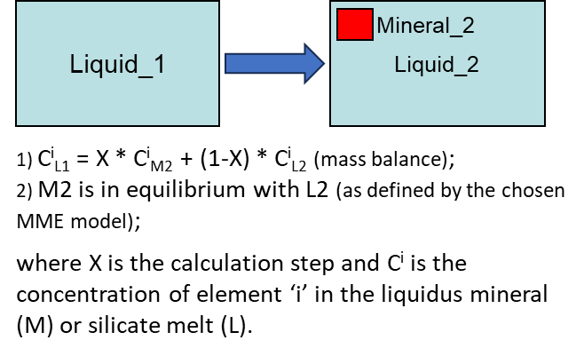
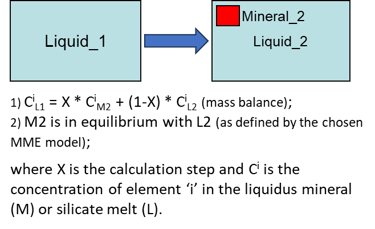
Figure 3. Fractional crystallisation equations for the case of a fluid- and sulphide-free system.
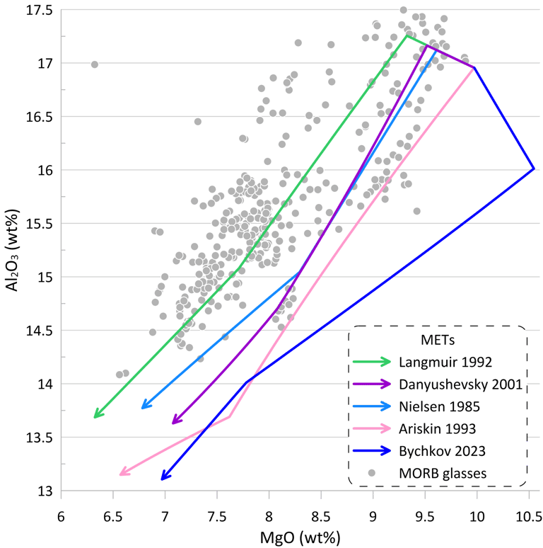
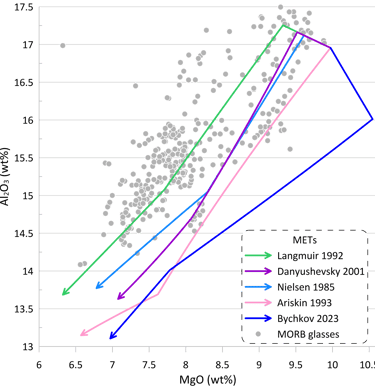
Figure 4. METs for a starting composition resembling an unfractionated anhydrous mid-ocean ridge-type melt were calculated using five sets of MME models for olivine, plagioclase and clinopyroxene: Nielsen (1985), Langmuir et al. (1992); Ariskin et al. (1993); Danyushevsky (2001) and Bychkov (2023). The METs were calculated assuming a fluid-free system, oxygen fugacity corresponding to the QFM buffer, and pressure of 1.5 kbar. The entire compositional range displayed by world-wide occurrences of mid-ocean ridge glasses with H2O contents < 0.25 wt% is shown for comparison..
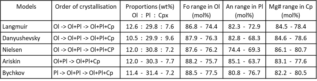
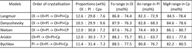
Figure 5. Order of crystallisation, and mineral proportions and compositions for the five METs shown on Fig. 5. Ol – olivine; Pl – plagioclase; Cp – clinopyroxene.
Individual MME models are usually developed for a limited range of melt compositions and/or intensive parameters (e.g., pressure, fO2, etc.), and thus the user can choose MME models to be used in specific calculations that are best suited for their compositions and/or crystallisation conditions. In other words, modelling crystallisation of different magma compositions at different conditions would normally involve different sets of MME models.
Petrolog4’ algorithm is designed to give the user a tool for assessing the applicability of available MME models for their needs, and the overall reliability of the currently available models.
Unlike the MME models, available models describing H-O-C fluid – silicate melt and sulphide melt – silicate melt equilibrium also require temperature as one of the input parameters. As a result, modelling these equilibria requires that at least one silicate / oxide mineral is included in calculations to determine crystallisation temperature.
Petrolog4 (v.4.0.6) offers 3 models of H-O-C fluid – silicate melt equilibrium and 3 models of sulphide melt – silicate melt equilibrium.
Modelling fluid- and sulphide melt-silicate melt equilibria requires that a silicate melt of a given composition can be assessed for fluid and sulphide saturation at every calculation step. Petrolog4 (v.4.0.6) offers 3 models of H-O-C fluid saturation and 5 models of sulphide saturation of silicate melts. Modelling crystallisation of a fluid-saturated silicate melt requires that the chosen models of fluid saturation and fluid – silicate melt equilibrium are self-consistent, whereas there is no such a requirement for modelling crystallisation of a sulphide-saturated melt with the currently available models.
Modelling fractional crystallisation in a fluid- and/or sulphide-saturated system involves, at each step, calculating PLTs of the current melt composition for all minerals involved in calculations, identifying the liquidus mineral, and solving the following equations (Fig. 6).
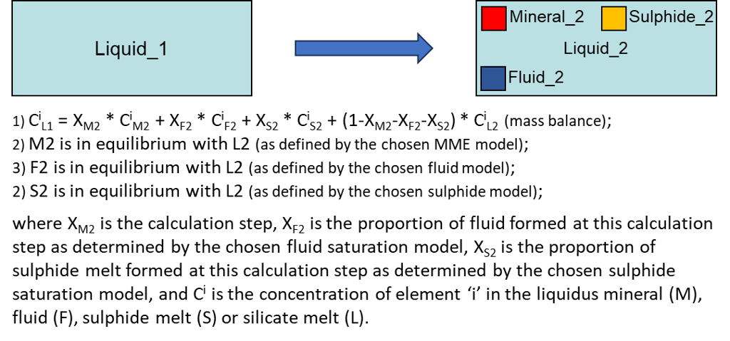
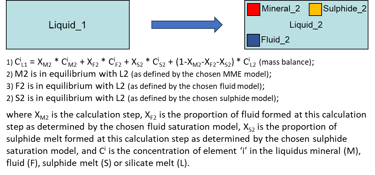
Figure 6. Fractional crystallisation equations for the case of a fluid- and sulphide-saturated system.
Like with the MME models, Petrolog4’ algorithm is designed to give the user a tool for assessing the applicability of available fluid and sulphide saturation models for their needs, and the overall reliability of the currently available models.
Equilibrium crystallisation
Modelling equilibrium crystallisation (i.e., when the crystals remain in the magma and continuously change their compositions as crystallisation proceed) in a fluid- and sulphide-free system also involves, at each step, calculating PLTs of the current melt composition for all minerals involved in calculations, identifying the liquidus mineral, and solving a more complex set of equations (Fig. 7).
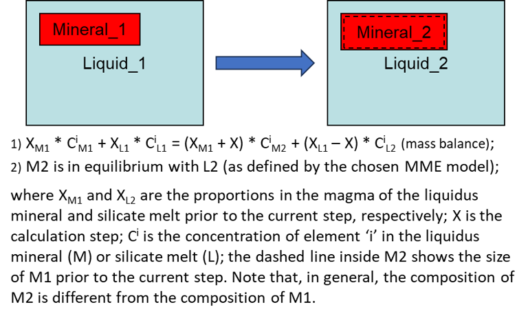

Figure 7. Equilibrium crystallisation equations for the case of a fluid- and sulphide-free system.
Unlike the case of fractional crystallisation, modelling equilibrium crystallisation requires that each step also involves:
1) an assessment of whether a peritectic reaction occurs during the step.
A peritectic reaction occurs when crystallisation of a mineral leads to dissolution of another mineral. The assessment of whether peritectic occurs involves analysis of the slopes of the PLTs along the direction of change of the melt composition during the step. The change in the melt composition reflects subtraction of the liquidus mineral (i.e., the difference in composition between L1 an L2, Fig. 7). A peritectic reaction occurs when the PLT of another mineral present in the magma decreases more rapidly that the PLT of the liquidus mineral along the direction in which the melt composition is changing (Fig. 8). This mineral will dissolve into L2 until its PLT reaches the PLT of the liquidus mineral. If more than one mineral satisfy the peritectic assessment (not shown on Fig. 8), it is taken that the mineral with the steepest PLT slope participates in the reaction at this step.
Note that whether a peritectic reaction occurs during calculations is entirely determined by the shapes of the liquidus surfaces of the MME models chosen for the calculations. Changing MME models may affect peritectic relationships between minerals during calculations.
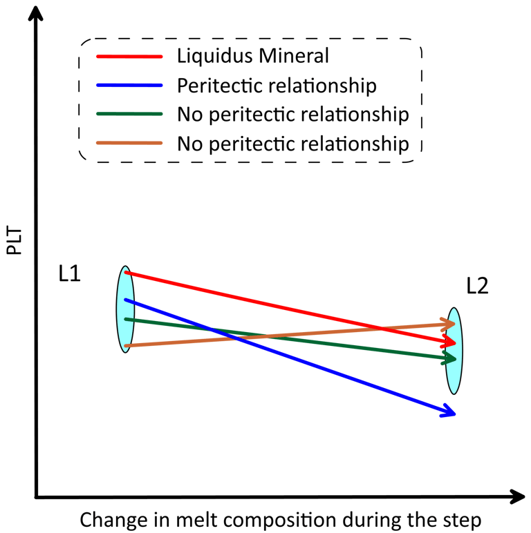
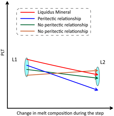
Figure 8. Schematic representation of the changes in PLTs during a crystallisation step when peritectic occurs. The size of the L1 and L2 symbols in the vertical direction reflects the uncertainty in the melt liquidus temperature when more than one mineral exists in the magma, which is < 0.1 degrees when the calculation step is 0.001 wt% of the amount of melt. See text for details.
2) an assessment of whether a mineral present in the magma would dissolve during the step due to a change in magma physical parameters.
This may occur during magma ascent when minerals with a strong dependence of PLTs on pressure (e.g., pyroxenes compared to olivine and plagioclase) would preferentially dissolve into the melt, or minerals that crystallise when water is present in the melt (e.g., amphiboles and mica) would dissolve when magma ascent leads to degassing of an H2O-bearing fluid.
When a peritectic reaction and/or mineral dissolution occur during a crystallisation step, the complete mass balance equation for such a step in a fluid- and sulphide-free system also involves the peritectic mineral and the dissolving mineral (Fig. 9). Depending on the extent of mineral dissolution, the amount of melt may increase during a step of equilibrium crystallisation.
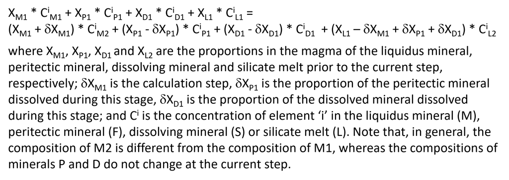
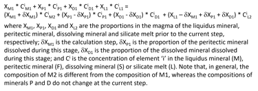
Figure 9. The full mass balance equation of equilibrium crystallisation for the case of a fluid- and sulphide-free system, that is solved at each crystallisation step.
Modelling equilibrium crystallisation in a fluid- and/or sulphide-saturated system requires solving a set of equations that includes those for the case of a fluid- and sulphide- free system (Figs. 8 and 9) and the equations for equilibrium between silicate melt and sulphide melt and fluid (Fig. 6). The mass balance equation (Fig. 9) is expanded to also include fluid and sulphide melt on both sides. Similar to the liquidus mineral, the compositions of fluid and sulphide melt change during each step.
Modelling trace elements
Petrolog4 considers Si, Ti, Al, Fe, Mn, Mg, Ca, Na, K, P and Cr as major elements. Concentrations of major elements in all phases can only be defined by the models of phase – silicate melt equilibrium. If a chosen model for a phase does not involve a major element, the concentration of this major element will be set to 0 in that phase.
Petrolog4 allows the user to include another 48 elements into calculations (the full list is given in the Petrolog4 Manual). Petrolog4’s algorithm allows for three different approaches for including trace elements in calculations:
1. Some of the phase – silicate melt equilibrium models incorporate some of trace elements. When such models are included in calculations, by default the concentrations of the included trace elements will be calculated in these phases following the approach used in the chosen model.
2. Petrolog4 can include an unlimited number of models that define distribution coefficient (D) values for an element in a phase as a function of various parameters, such as melt composition, temperature, phase composition, etc. If such models are selected for any of the trace elements that are included in the chosen phase – silicate melt models, this will lead to concentrations of the affected elements being calculated using the D model, not the phase – silicate melt model. Petrolog4 (v.4.0.6) offer 5 such models: 3 for Ni in olivine, one for Ba and Sr in plagioclase, and one for reduced and oxidised S in an H2O-CO2 fluid. More models will be included in future releases of Petrolog4. Licenced users can request inclusion of specific models.
3. The user can enter a constant D value for a trace element in a phase, which will be used in calculations to determine the concentration of the trace element in the phase. If constant D values are selected for any of the trace elements that are included in the chosen phase – silicate melt models, this will lead to concentrations of the affected elements being calculated using the constant D value, not the phase – silicate melt model.
Concluding remarks
The range of magma compositions and crystallisation conditions that can be modelled by Petrolog4 is limited by the availability of published phase – silicate melt equilibrium models.
Petrolog4 (v.4.0.6) does not include any models for amphibole, mica, alkali feldspar, quartz and apatite. This does not allow for modelling of anhydrous diorite – rhyolite compositions and hydrous andesites – diorite – rhyolite compositions.
Other Petrolog4 Options
Petrolog4 (v.4.06.) also offers tools for
- determining melt liquidus association;
- modelling the reverse of fractional crystallisation; and
- modelling diffusive re-equilibration of melt inclusions in olivine.
Plans are in place to add in future releases tools for
- normative mineralogy calculations;
- modelling U-Th-Pb equilibrium decay in closed and open systems; and
- modelling laser-ablation ICP-MS signal on quadrupole instruments during ablation of micro-inclusions.
These tools will be described in subsequent presentations.